How to Read a Septic Design Drawing
Last updated: October 24, 2026
Quick Answer: How to Read a Septic Design Drawing in one line: check the title block, legend, elevations, and flow path first, because those four items tell you where the tank, distribution box, drain field, and reserve area go. A septic design drawing tells you where the septic tank, distribution box, drain field, and reserve area go, how deep the pipes run, and how the system fits the site. If you can read the symbols, contour lines, and elevation marks, you can follow the design conversation instead of guessing at it. How to Read a Septic Design Drawing starts with the plan, not the parts.
Key takeaways
- Start with the title block and legend so you know which plan you are looking at and what each symbol means.
- Read the site plan next: property lines, house location, setbacks, slopes, and the septic components sit in relation to one another.
- Check elevations and pipe slopes before you look at the drain field layout; those numbers tell you whether wastewater can move by gravity or needs a pump.
- The tank placement, distribution box, and reserve area matter as much as the drain field itself.
- A homeowner can learn the drawing well enough to ask better questions, but final design decisions belong with the engineer or local reviewer.
What a septic design drawing shows first
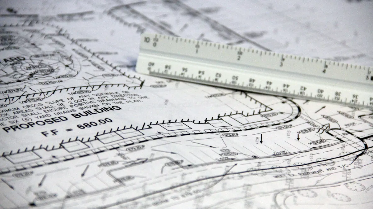
A septic design drawing shows the whole system on a site plan, usually at a scale such as 1 inch = 20 feet or 1 inch = 30 feet, so the site can be read as one picture. The first thing to find is the title block or label strip, because that tells you whether you are looking at a preliminary sketch, a permit set, or a revision. For How to Read a Septic Design Drawing, that first pass is the fastest way to avoid reading the wrong sheet.
Start here:
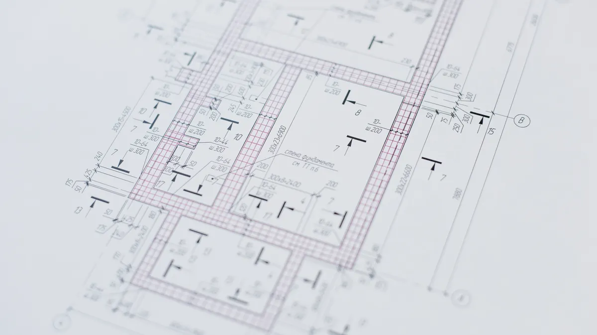
- Find the title block and read the project name, parcel address, date, and drawing number. That tells you whether the sheet is current or a superseded revision, and it keeps you from using an old layout by mistake.
- Locate the north arrow and scale bar. Those two items let you orient the plan on the lot and judge distances instead of eyeballing them.
- Read the legend. Symbols for the septic tank, distribution box, inspection ports, and drain field trenches often look like shorthand marks until the legend translates them.
- Trace the house, driveway, wells, streams, property lines, and setbacks. When the plan is working, the septic system sits inside the usable portion of the lot with clear separation from sensitive features.
A good reading of this first layer should let you answer a simple question: “Where does the system sit on the property, and what nearby features control its location?” If you cannot point to the lot lines and the house on the drawing, you are not reading the system yet; you are just looking at symbols.
This is the right point to compare the drawing with a septic system types and sizing guide, because the layout only makes sense once the system capacity and basic type are known. The drawing does not replace that bigger design context.
How do I read the site plan, contour lines, and elevation marks?
You read the site plan by using contour lines and elevation marks to see which way the land falls and how much room the system has to drain or pump. The contour lines are the backbone of the drawing, especially on sloped lots where a 2-foot change in grade can make a big difference.
Look for these items in order:
- Contour lines. These curved lines connect points of equal elevation. Tight spacing means steeper ground; wide spacing means gentler ground. If the lines crowd together across the proposed drain field, that part of the lot may be too steep for a simple layout.
- Spot elevations. These are single numbers placed at points such as the house slab, tank inlet, or top of a trench. A spot elevation gives you an exact height, usually in feet above a project datum.
- Finish grade and existing grade. “Existing” shows the land before work. “Finish” shows the intended surface after installation. If the drawing includes both, the difference tells you where soil will be cut or filled.
- Slope arrows or percent slope. Some plans use arrows; others use percentages. A slope note explains direction and steepness in one glance.
The key idea is vertical control. Wastewater does not care that a trench looks wide enough on paper; it cares whether the pipe can maintain the right fall from the house to the tank and from the tank to the distribution box, or whether a pump is needed. A common gravity line slope is often shown as a small percentage rather than a large drop, so do not mistake “small” for unimportant.
A drawing works when the elevation marks line up with the proposed flow path. If the tank inlet is lower than the house outlet, or if the drain field sits upslope without a pump or dose design, the plan should raise questions immediately.
Follow the flow: tank placement, pipe slopes, and the distribution box

You follow the flow by tracing wastewater from the house to the septic tank, then to the distribution box, and out to the drain field. This is the most practical part of the drawing, because it shows whether the system is gravity-fed, pumped, or split between both.
Read the run in this order:
- House sewer line. Find the line leaving the building. Its diameter is often shown in inches, such as 4 inches for a building sewer, though the exact size should match the plan notes. The line should move downhill or at the specified slope toward the tank.
- Septic tank. The tank symbol usually sits between the house and the dispersal area. Check its orientation: inlet on one side, outlet on the other. If the tank is rectangular on the plan, the long side does not automatically tell you flow direction; the inlet and outlet labels do.
- Tank setbacks and access. A useful plan shows the tank far enough from the house, property boundary, well, or driveway to meet local rules. The drawing should also show risers, lids, or access ports if they are part of the permit set.
- Distribution box. The distribution box, or D-box, splits effluent into multiple laterals. It should sit where the outlet line from the tank reaches it cleanly and where the trenches fan out evenly. If one trench is much shorter than the others, the box may need adjustment.
- Pipe slope notes. Look for numbers like 1/8 inch per foot or a percent slope. These figures matter because the pipe must move flow without outrunning solids or sitting flat in a way that traps waste.
A plan is easier to trust when the arrows, labels, and slope notes all agree. If the line from the tank to the D-box crosses a contour the wrong way, or if the arrows point opposite the labeled inlet and outlet, stop and ask for clarification. That kind of mismatch is not a minor drafting issue; it can change how the system performs.
How do I understand the drain field layout on a septic design drawing?
You understand the drain field layout by reading the trenches, their spacing, their direction, and the reserve area as one package. The drain field is not just a blob on the page; it is a set of measured lines that must fit the site and the required capacity.
Look for these parts:
- Trench lines or bed outline. These show where the absorption area will be installed. On one plan, you may see several parallel trenches; on another, a single bed or chamber layout.
- Trench length and spacing. The drawing may label each trench length in feet and the distance between centerlines or edges. Equal spacing helps distribute flow evenly from the distribution box.
- Orientation to contours. Trenches often run along the contour rather than straight down the slope so effluent spreads more evenly. If the trenches cut sharply across steep contour lines, that can signal a design problem or a pumped system.
- Reserve area. The reserve area is the backup space set aside for future replacement or expansion. It may be labeled as a future field, replacement area, or repair area. It should be on usable ground, not left as a vague blank corner of the lot.
The reserve area is easy to miss, but it matters. A drawing that shows a nice primary field and no real backup area is incomplete in practice, even if the sheet looks polished. If the reserve area overlaps a driveway, a large tree, or a retaining wall, that is a warning sign that the lot may be tighter than the plan admits.
A correct layout also shows that the field fits inside setbacks from wells, streams, property lines, and structures. Those distances are not decoration. They are the difference between a usable permit drawing and a sketch that never passes review.
Signs the drawing is clear — and signs it needs a second look
A clear septic design drawing gives you enough information to trace the system without guessing. A weak drawing hides that information behind vague labels, missing elevations, or cramped symbols. This is the section that saves time during the design conversation.
A good drawing usually includes:
- a readable legend with the septic tank, D-box, drain field, and any pump components
- contour lines with enough spacing to show the lot’s shape
- elevation marks at the house, tank, field, and key pipe junctions
- a reserve area drawn to the same standard as the primary field
- notes that identify the scale, revision, and date
A shaky drawing often leaves out one of those items. A common problem is a field outline with no trench lengths, which makes it impossible to tell whether the layout matches the intended loading. Another is a plan that marks the tank but never shows the direction of flow. If the inlet and outlet are not obvious, the drawing is asking the reader to assume something that should be explicit.
The cost of misreading a plan is usually not theoretical. It can mean bad questions in a permit meeting, delayed approvals, or a contractor building from an assumption instead of a measured layout. The fix is simple: slow down, trace the flow, and compare every symbol against the legend and notes. For a permit review, that can save one revision cycle and avoid a second submittal.
This is also where an engineer’s mark-up matters. Handwritten revisions, clouded areas, and changed dimensions usually mean the drawing has already gone through at least one correction cycle. Do not ignore those marks; they often point to the exact part that required redesign.
How to talk about the plan with an installer or engineer
You talk about the plan by asking about the specific items that control performance: tank placement, pipe slope, field layout, elevation marks, and the reserve area. That keeps the conversation grounded in the drawing instead of drifting into guesswork.
Use the sheet to ask direct questions:
- Is the septic tank located at the elevation needed for gravity flow, or does this plan require pumping?
- Are the trench lengths and spacing shown here the final values?
- Which contour lines control the field placement?
- Where is the reserve area, and is it buildable later?
- What changed in this revision compared with the last one?
If you can point to the exact line or note on the page, the discussion gets better immediately. A good professional can answer from the drawing itself and explain why a feature is there. That matters because the plan is not only a permit document; it is the map for the work to come.
A homeowner should also know what the drawing is not. It is not a substitute for the site evaluation, and it is not a construction guide that explains every excavation detail. It tells you where the system is meant to go and how the pieces relate, but it does not replace the judgment that goes into soil testing, sizing, or installation sequencing. For that broader context, the hub on septic system types and sizing is the right companion page.
If the drawing feels confusing after one careful read, that does not mean the plan is bad. It often means the lot is tight, sloped, or full of constraints. Those are exactly the cases where a clear drawing matters most.
What symbols appear on septic plans?
Septic plans usually show the septic tank, distribution box, drain field trenches or bed, property lines, house footprint, wells, setbacks, contour lines, and spot elevations. Some drawings also include inspection ports, cleanouts, pump chambers, and reserve areas. The exact symbol set depends on the drafting standard and the local reviewer, so the legend is the first place to check. For example, a 4-inch building sewer or a 1/8 inch per foot slope note may be written in compact drafting shorthand.
Who reviews a septic design drawing?
A septic design drawing is typically reviewed by the local health department, environmental agency, building department, or another authority with septic permitting power. In many cases, an engineer or designer prepares the drawing, then a reviewer checks it for code compliance and site fit. The homeowner usually reviews it informally with the installer or engineer, but does not approve it alone. According to the U.S. Environmental Protection Agency, onsite wastewater systems are often overseen at the state or local level, and permitting requirements vary by jurisdiction. See the EPA’s guide to septic systems and the National Environmental Services Center’s overview of onsite wastewater treatment.
Can a homeowner understand a septic plan without an engineer?
Yes, a homeowner can understand the main layout, flow path, and reserve area without being an engineer. The plan is still technical, though, and the details that decide approval—such as slope, elevation, and setback compliance—can be easy to misread. A homeowner can learn enough to ask sharp questions, but final interpretation should stay with the design professional. A quick read can help, but a permit set is still measured in feet, inches, and slopes, not impressions.
Quick comparison: what to check on a septic design drawing
| Item | What to look for | Typical number or note |
|---|---|---|
| Title block | Project name, date, drawing number | Current revision date |
| Scale | How the lot is measured | 1 inch = 20 feet or 1 inch = 30 feet |
| Building sewer | Pipe leaving the house | 4 inches |
| Pipe slope | Direction of flow | 1/8 inch per foot or percent slope |
| Contours | Ground shape and steepness | 2-foot change in grade can matter |
| Drain field | Trenches or bed layout | Lengths and spacing shown in feet |
| Reserve area | Future replacement space | Labeled future, replacement, or repair area |
Related reading
- Septic system types and sizing
- Septic permit process
- Septic system maintenance
Drafted with AI; not yet reviewed by a person.